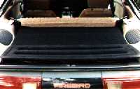
Shown here is the area between the rear seat and subwoofer enclosure before installation of the amp rack.
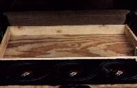
Shown here is the area between the rear seat and subwoofer enclosure with the frame of the amp rack in place awaiting installation of amps and other accessories.
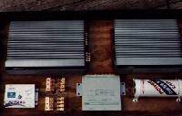
Shown here is the amp rack with components placed for a 'dry fit' before drilling of wireing holes and laying of carpet.
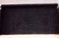
Shown here is the amp rack with the carpet and fan network in place. The fans are set up so that the passenger side blows air into the amp rack, and the drivers side fan pulls air out of the amp rack to facilitate maximum flow. The Generation X series of HiFonics amps utilize thermal tracking which will activate the ground terminal the fans are connected to as the amps require cooling.
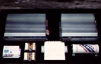
Shown here is the amp rack with the components in place before wireing.
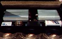
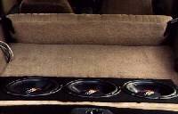
Shown here is the amp rack in place behind the rear seat of the vehicle
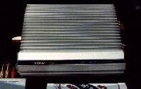
Shown here is the HiFonics 'Generation X' Saturn. This unit has an optional input/crossover endcap installed to allow for built in control of highpass/lowpass settings. Rated at 60X4, 2 channels are dedicated to the set of USD D2 waveguides and 2 channels are dedicated to a 5 1/4" and 6 1/2 set of Audio Art midrange and midbass drivers.
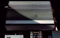
Shown here is the HiFonics 'Generation X' Thor. Rated at 125X2 the amp is dedicated to 3 Petras Hyperthrow 10" subwoofers. Both HiFonics amps incorporate 'Stealth Thermal Tracking' and will activate the fan network if either amp detects that it is about to go into a thermal shutdown mode.
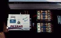
Shown here is the Petras 'Mr.Q' Bass processor, 2 Bostwick power distribution blocks and a Bosch relay. The relay is used to feed 'fresh' 12-volt power to the fan network and remote turn on terminals on the bass processor and amps. The relay is activated by the remote turn on lead from the Clarion head unit.
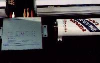
Shown here is the Clarion DPH-7100 EQ/DSP unit and a Gel-America 1 farad stiffining cap. The 4-guage power routed from the battery runs to the cap then from the cap to one of the power distribution blocks.
Shown here is the amp rack with the cover in place. Attached to the top of the amp rack is the factory 'trunk lid' used for a stealth cover of the subs when the hatch is closed.
| Copyright ©Russell A. Hatfield, 2001-forever |
This site is designed for a resolution of 800X600 or higher.