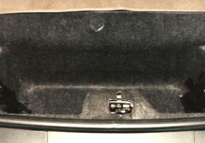
| Shown here is a view of the hatch area prior to laying the fiberglass
shell of the subwoofer enclosure. This particular vehicle is equiped
with t-tops which led to the removal of the t-top storage racks
In this photo you can see that the mounting bolts were covered to
prevent the fiberglass from forming around them and locking the shell
into place.
|
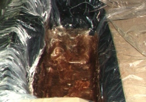
| Shown here is a view of the hatch area after laying a plastic drop
cloth and having laid a layer of fiberglass into the storage well.
|
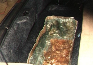
| Shown here is a view of the subwoofer enclosure shell after laying 2-3
layers of fiberglass and trimming the top edges.
|
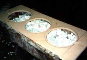
| Shown here is the process of measuring the final volume of the subwoofer
enclosure. Packing peanuts were used to fill the enclosure via a
pre-determined volume box used as a 'measuring cup'. Final enclosure
volume was calculated to be approximatly 1.56 cubic feet.
|
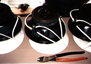
| Shown here is a view of the subwoofers wire termination, all connections
were soldered and heatshrunk. Pollyfill was added to the encolsure.
|
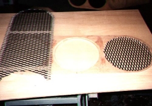
| Shown here is a view of the grill construction. Wire mesh was cut to
fit countersunk holes in a piece of 1/2" wood.
|
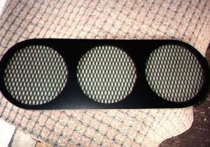
| Shown here is a view of the back of the sub grill. The metal mesh
was painted to match the car, black formica was used for a clean
look after the grill cloth was attached.
|
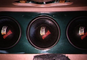
| Shown here is A picture of the trim ring over the subs. 1/4" wood was
cut to allow the gaskets and screws holding the subs in place
to be concealed. The ring was painted to match the car.
|
|
This site is designed for a resolution of 800X600 or higher.
|